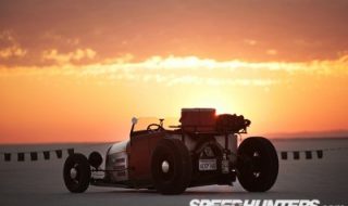
Bonneville Salt Flats Inspired Hot Rod Thanks to Speedhunters.com for this beautiful shot of Rex's amazing Lakes Modified roadster at Speedweek 2009. If you had the engineering and fabrication skills of Rex Schimmer, how would you build a Model A roadster? If (or when) I build a roadster, it could look much like this 1929 Lakes Modified Ford roadster! Rex is actually a MyRideisMe.com member. You can see his MyRideisMe Garage and make his ride one of your favorites and put him in your "crew" like I did. Rex's roadster is unmistakeably a traditional style Lakes Modified build, but it is also very unique and one of a kind. Read on to find out exactly what went into this 7 year project, which culminated in the ultimate drivable roadster you see here. Rex: How did I get into cars? Been a car guy since I was 11 or 12. I started reading the "small" magazines, Rod and Custom, Car Craft, etc. around 1955 and bought my first car, 1953 Ford Victoria hardtop in 1958. I dropped it using dropped spindles, cut coils and a de-arched spring, removed the hood and trunk chrome, frenched the head lights...
1933 Ford Pickup Gets Salty at Speedweek 2009
posted by Hechtspeed
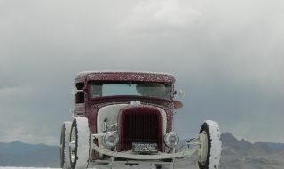
Bonneville Salt Flats Hot Rod: One piece of the Bonneville Speedweek recipe that can't be forgetten is the get together on Friday and Saturday night at the Golden Nugget in Wendover. From a Salt insider, the Nugget Car Show is not an official car show. You won't find any websites announcing the Car Show, but it just sort of happens. It has become a tradition. Enter Jerry Armijo and his 1933 Ford Pick up hot rod. As I was strolling the Nugget parking lot soaking in the hot rods, I saw this pick up full of Salt. It was not the only hot rod with salt covering it, but it appeared to be the rod with the most. One of my favorite parts of the Bonneville Salt Flats is how the salt gets everywhere. These open wheeled hot rods are especially good at flinging the salt. I started snapping pictures of this rod and how the salt was basically covering the windshield when I met Jerry, the proud owner.Here's what I found out about this cool ride. It's a 1933 Ford Pick up. When...

5 Tips for Building a $5000 Pro-Touring Mustang
posted by Hechtspeed
1966 Mustang Fastback - Pro-Touring Budget "I bought a 1966 Mustang Fastback out of a junk yard for $400. Thought I would challenge myself to build as exotic a g-machine as possible for $5000. " It sounds impossible, anti-Pro-Touring even. MyRideisMe.com asked Ron Schwarz, owner/builder of this Grabber Blue beauty, to share his 5 Tips with our readers. He tells it like no one else can. This guy is hilarious! There are some killer classic quotes here. Stick to these 5 Tips below and you too can build your own budget dream ride. 1. Choose The Right Car Your car has to be affordable, but still turn you on. If it doesn’t keep your interest it will be just another project that doesn’t get finished. Choose a car you can get cheap parts for, period. 2. Do your homework The mods on this Mustang were done with factory (Ford and GM) parts from performance models/sports cars. The front suspension is all C5 Corvette parts; great handling, big brakes, relatively cheap, and fairly easy to come by. 3. Choose The Right Drivetrain. Find a drivetrain that...
“Dear Welder Series…” Tech Help Introduction
posted by WelderSeries
Here at Welder Series, we get emails. We reply to emails. All of them. Even those nice people who want to see me more satisfied. (What's a "male product", anyways? Am I a product of my own imagination?) Anyways, I thought some of these tech type emails would be beneficial to more of you than solely the person who penned keyed the question. Onward. Dear Welder Series... "Hi there, I recently purchased one of your triangulated 4-link from Horton's (www.horton.on.ca). I am currently building a 28 Model A Tudor and I am building my own frame. I'm about ready to start fabricating the rear section of the frame and I was wondering if you can give any tips on how to rig up the rear suspension/frame so I can get the car as close to the ground as possible without loosing to much headroom since the car is going to be chopped. I will be running 32" tall rear tires and I would like the frame to be about 5 inches off the ground (at the floor before the rear Z). Also, I will be channeling the body. Thanks...
Welder Series frame curve review by J.F. Launier
posted by WelderSeries
Simple product is Canadian made How often are simple projects truly simple? Almost never is the correct answer but I have discovered a great product that is just that. After a very eventful outdoor show season. My first item was to get back in the shop and work. My wife and I put over 75,000 kms on our diesel truck heading from show to show this year and it’s time to get my hands back on some tin. So there I was, thinking about my next project. To keep it moving forward, I’d need to put a frame under the thing. Then it dawned on me, how cool it would be to try to keep this build Canadian. It will likely be next to impossible to keep it ALL Canadian but you have to start somewhere. If you went to SEMA this year, you very likely would have stopped by the Speed Tech Performance booth. Not only are they Canadian but they’re from right here in BC! (Maple Ridge to be exact.) They make really nice 1st and 2nd gen Camaro subframes and other cool suspension stuff. Off to...
How-To: Custom Bumper Guards on a 1950 Merc
posted by Hechtspeed
All Ways Hot Rods, located near downtown Phoenix, was founded in 1999 by the Way brothers Mike and Randy. They help hot rodders build their dream cars. One of those dream cars you may be familiar with is a flawless 1932 3 Window Coupe that won the 2008 Goodguys "America's Most Beautiful Hot Rod" award. In this shoebox how-to we'll take a look at how Gregg Grisham, a long time member of the All Ways team gives the custom touch to a '50 Merc's front and rear bumper by adding '51 Merc' bumper guards. Let's listen in to the how-to instructions from Gregg: "This method will work for most combinations. I need to mention that it is important to clean off the chrome and copper from where you are welding, and to make the surfaces of your welds as pit free as possible, and a good chrome shop like Kerr West can do wonders to finish off the parts. Here's a list of the Chop Shop Tools All Ways Hot Rods used: Rolloc grinder with various pads to clean chrome and grind for fit, 45 degree with cutoff wheel...
Creative Workshop Sport Speciale – No Sale!
posted by pikesan
Submitted by Jason Wenig from The Creative Workshop, a restoration and full service coach builder out in Florida. An interesting turn of events transpired this past weekend. As you are probably aware, last week was the "big auction week" out in Scottsdale, AZ (culminating on Saturday night), where all of the major car auction companies display and sell a dizzying array of vehicles. On top of the grandeur of these events, in many ways, it can be said that this past week sets the tone for values and trends for the coming year. As a car builder, I walk a thin line. I personally am not a big fan of the auctions - I don't sell cars - I build them, but it is hard not to at least be interested, and in many instances, it is important for me to understand where people's money is going - what types of cars, what eras, etc are being sold… if not just for business, then certainly for my own love of cars! Which brings me to my story: My Client, (Arizona's own, car collector) Barry Smith, decided to get the...

Bonnie’s Inteior Update – 27 Ford Rat Rod?
posted by pikesan
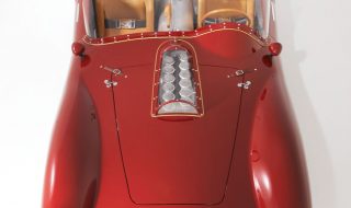
It's about time I update everyone on the interior upholster on my 27 Ford Roadster. Now that the interior is done, is it a rat rod? I didn't really think it was before, but who really cares. Now it's got car carpet, a full seat and even sound insulation! The interior was done by Todd over at "The interior Shop" in Phoenix. Todd was challenged by the inside of the modified roadster because there isn't really much to secure the interior to and there's also some funny compound curves. In the end, I think it came out great! It looks like leather, but it's not. It's a distressed looking vinyl that's perfect. When I put paint on, it's gonna be cool and not your every day blood red. Below are the rest of the shots. Thanks to everyone that voted for "option B" as drawn by Jimmy Smith from Jimmyshotroddesign.com. Here's the link to that story if you missed it: 27 Roadster Interior you chose...
1964 Morris Minor Custom – UK Style
posted by pikesan
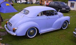
Minnie the Moocher 1964 Morris Minor 2 door sedan (See the Custom Morris Minor) Written by: "Tootall" Paul from Cornwall, United Kingdom ‘Minnie’ is my Wife’s ‘64 Morris. She had wanted a kustom for a while and has a particular taste for ‘round’ cars. When one of our clubmates (We are members of UK Kustoms) suggested a Minor we looked harder at them and realized that one would make a great sled. When we were told that if we could find one before the 2002 NASC Nationals then the club would chop it for us, the search was on. We bought her from a young chap who made us promise that we would look after her. We assured him that we would take great care of her and we have – though maybe not quite in the way he would have expected. We had owned her for 2 weeks before we drove her the 300 miles to the Nationals. She was driven there on Friday, stripped of her glass and interior on Saturday, chopped on Sunday and, with a plastic windscreen installed, driven the 300 miles home again on...
240Z Street Racer Oil Cooler Install
posted by BlueovalZ
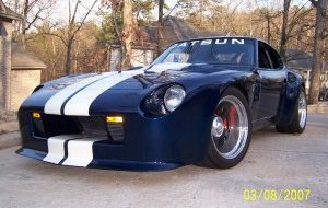
When I had the 289 CID motor in this car, engine oil temperature was not a problem and at times it ran cool. The installation of the 383 (stroked 351W) changed all of that. Any extended driving or repeated hard acceleration would push the engine oil temperature up to 240º, and sometimes to the end of the gauge at 250º. Water temperature appeared to be stable, and no more than a couple of degrees warmer than with the smaller motor, so it appeared I had to remedy an oil temperature problem. Some of the options for mounting the cooler were: 1) In front of, or behind the radiator which created problems directing the oil supply hoses to and from the cooler. The design of the car has the engine radiator sealed by body/hood panels to ensure forward motion air pressure is forced through the radiator with minimal losses around it. Attaching the oil cooler to the radiator would require cut or modified body panels, extended lengths of hose, and the general dissatisfaction of having a cooler attached to the radiator through the fins using the typical plastic fasteners. The...
Holman & Moody Boss 429 – (you should read this)
posted by pikesan
The first step in fixing a problem is admitting you have one. Hi, I’m Craig, I don’t know crap about bodywork. (Hi Craig). With that out of the way, I moved onto the next step. That’s seeking help. I turned to my new friends over at Squeeg’s Kustoms in Mesa, Arizona. Squeeg’s has been turning out show quality paint and bodywork since 1964 and Doug Jerger, the owner and Squeeg’s son, has kept the business rolling. One of Doug’s latest paint jobs was for his America’s Most Beautiful Roadster (AMBR) contenting 32 Roadster. I was in good hands for my shotgun lesson in body work to support the 63 Falcon Wagon project. When hot rods and custom car building’s in your head nearly every waking minute, hanging out in a shop like Squeeg’s might as well be Disneyland. When I pulled up, Doug and the Jerry Courlton were standing out front marveling at the fresh custom paint on Jerry’s Corvette super gas race car body. Wow. It’s tough to put down this many colors without having that, “I’m stuck in the 80’s” look, but Doug nailed the graphics and...
Eddie Paul: Learning Sheet Metal Fabrication from a Master
posted by Bubba Harmon
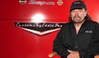
Sheet Metal Fab Book Eddie Paul is one of those rare individuals who can do almost anything. In fact his motto is, “If it doesn’t work, it just isn’t finished yet”. Often characterized as a serial inventor, Eddie has many patents in various fields. Some of his clients over the years include the Department of Defense, Department of Energy, Boeing , Rockwell, Mission Research, SOCOM, and the Department of Forestry to name a few. He’s been a stuntman, actor, and stunt coordinator for many movies and TV shows. Need a shark? Eddie has built them for the Cousteaus and the Discovery Channel. Need some tools? Eddie’s shop builds many for the Eastwood Company including their English wheel and planishing hammer kit. The works most people will recognize though are all the vehicles Eddie’s shop has produced over the years for countless movies, TV shows, and commercials. A short list includes the cars from Grease, the original Dukes of Hazard stunt cars, the stunt chopped Mercs for Cobra, various cars for CHiPS, Triple X’s custom ’67 GTO, the custom Crown Victoria taxis in Taxi, all the vehicles in The Fast...