Ride Nickname:
BlueOvalZ
Make:
Datsun
Model:
240Z
Year:
1971
Introduction / Overview:
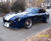
1971 Datsun 240Z that became a divorce recovery project. After dropping the SBF engine into the car, I found that the high speed stability was less that I could bear, so I created a body that idecreased the lift at the higher speeds (actually, it provides a bit of downforce overall). Currently the car is no longer a track car. I fabricated a fiberglass dash, installed some more comfortable seats, headlights, and other things needed to allow me to register and license the car for street use. It still has the full cage and door skins, so yes, I still have to crawl through the window to get in.
Drivetrain:
Ford 289 which is very soon being replaced with a 383 (Not the Chevy, but the Ford 351W stroker version). Home-made headers, AFR 205 heads, and the typical go-fast internals. The engine is solidly mounted (along with transmission) into the chassis making is part of the chassis which greatly increased the chassis rigidity.
Transmission is a WC T-5 pulling to a Datsun R200 differential using Porsche 930 CV jointed half-shafts. Currently, at the rear wheels, the 289 dynos at 299 HP, and 260 lb/ft at 7200 RPM. It has a lot of RPM potential, but now I'm looking for more torque, and hence the reason for installing the 383. Hopefully, it will reach my design of mid 500 HP and torque fiqures at around 6500 RPM. The new heads, and almost 1" more stroke should get me close.
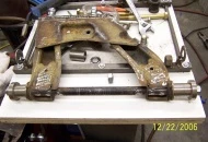
Chassis:
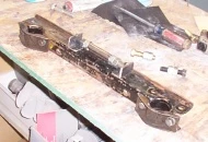
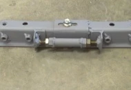
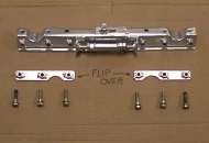
The chassis is still basic Datsun equipment. The front crossmember has been moved forward 1.25" to increase the caster for an improved camber curve. This meant that the T/C rod had to be increased in length as well. The inner bushings have been replaced with spherical rod ends on the front, with fabrication just completed for replacing all eight bushing on the rear suspension with 3/4" spherical bearings. The rear uprights and mustache bar have been replaced with a single 1/4" aluminum plate that mounts the differential, suspension, and swaybar all on one piece. The rear bushings are held independently onto this plate, separated by a turnbuckle, to allow toe adjustment of the rear wheels. Spring rate is 225 F/260 R using coilover set-up and Koni shocks.
Wheels:
17 X 11 Billet Specialties wheels with 315/35R17 tires an all four corners (DOT set-up).
Body:
Body is a home-made fiberglass creation painted in a GM Tahoe blue w/ Wimbleton white stripes
Interioir:
Fabricated out of fiberglass from a once fully gutted race interior.
Lifestyles:
Builder, Club Racer, Euro