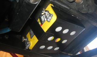
Building a Battery Tray for an Optima Battery Is there anything worse than when your car cranks, but doesn't start? (overheating must be a close 2nd) That was the deal with my 1927 Ford Roadster named Bonnie. Especially when I first put the dual Weber 44 carbs on, she was a little hard to start and wasn't afraid to flood if I wasn't careful. At the time, I was using a gel-type motorcycle battery. That worked out great because I could mount it anywhere (space is precious in a roadster!) but it was TINY! And... it never lasted long enough when extra cranking was needed. After one last jump-start at a cruise-in, I decided to step up to an Optima Battery. With some help finding their smallest & lightest battery I decided on the Group 51 Yellow Top (part number 8073-167). At 450 Cold Cranking Amps, it was double the output of the motorcycle battery I was using and will easily survive under the car and mounting on it's side. Why Yellow? Good questions! Choosing Red Top or Yellow Top Optima is a mistake alot of people make, so I'll...
Frank Lockhart’s Slick Speedster Reborn
posted by pikesan
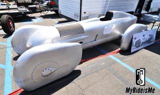
Land Speed Racer-Recreation at the LA Roadster Show You'll never know what you might see! Wandering the huge-anic swap meet at the LA Roadster Show, I found this: (Click to see full size) Feast your eyes on the not-quite-finished replica of Frank Lockhart's Stutz Blackhawk Special. Handmade and very accurate from what Ned told me to the original. It'll even run a special, rare-like-you-wouldn't-believe Miller 4 cylinder engines. (that's one reason it's not done yet) Why? I don't know... cause the owner can I guess! I wanted more info, but the guys were already loading the car into the trailer (you gotta see it in the pics below) when I showed up and with the sun beating down, it was all business for them. If you know more about the car, please get in touch. [nggallery id=66] To learn more about the original car and the crash that took the life of Frank Lockhart, here's a few links. You should know, at the time, Frank was the youngest Indy 500 winner and the record holder for most laps led from the start (81 Laps). Not to mention, the guy...
Ford Falcon Gasser – Nailed by Chuckles Garage
posted by Hechtspeed
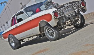
Straight Axle Ford Falcon Gasser Meet the Chuckles Garage "Strange Bird" 1962 Ford Falcon Futura A/GS drag car. This car started out as a $200 Craigslist beater and through some odd chain of events, became the "Strange Bird". MyRideisMe.com stumbled on Scotty Birdsall, owner and chief ornithologist at Chuckles Garage, a full service fab shop in Santa Rosa, CA. In Scotty's words, here's more info on this wicked Ford Falcon and what hits you first, the blown 401 Buick Nailhead: "The 'bird's powered by a Littlefield supercharged Buick 401 Nailhead originally in a 1960's drag boat. The Nailhead sports a shop-fabbed blower manifold, custom pistons & rods, a wild Comp Cams bumpstick and lifters, custom valve springs and hi-flow valves, mild port work, custom pushrods, custom headers made in-house, vintage Weiand valve covers, dual Buick Wildcat Rochester 4 Jets that were modified for use with the blower with custom linkage, Nicson front cover/engine mount, custom motor plate, custom oil pan, and is backed by a built Buick ST400 transmission from a 1965 Riviera." Can you say CUSTOM FALCON!!!??? Can't wait to hear what a blown Buick 401 Nailhead...
Subyrod Gets a New Exhaust
posted by Hechtspeed
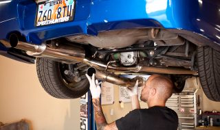
Subaru WRX Performance Mod Sup? Time to update you all on Project Subyrod, my 2002 Subaru Impreza WRX. I was getting really excited for Speed Week 2010, the Nugget Cruise in and everything that goes with being at Bonneville. For Subyrod's first trip to the Salt Flats, I felt an itch to have a custom axle back exhaust made for it, something that would turn some heads, maybe make my car fit in with all the old iron running around with loud exhausts. It had to be on a budget. I kicked around the idea and then dropped in at JDM Legends (See my Introduction Story of JDM Legends here) to see what Eric Bizek could weld up for me on a small budget. Take a look at some in-process photos below of the custom exhaust work. I was thinking of a few options, mild steel painted or stainless and 2.5" or 3". We ended up going with stainless 3" dia. tubing to match the rest of the exhaust system. One way to achieve my budget was using some of Eric's stainless scrap pieces laying around. Here's Eric Bizek of JDM Legends...
One Goodguy’s Roller Coaster Ride to Puyallup
posted by Brian
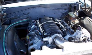
Buick Skylark's LS2 Engine Swap: Most car guys make like-minded friends, and Jason Rushforth is proud to know car guys all over the world. Take a half-dozen of his friends who live close by him in the Pacific Northwest, throw in some emotional roller coaster moments, one '64 Buick, a high-tech engine swap and a few late nights. From there, subtract proper nourishment and numerous hours from the daily schedule, and you get the story of some of the best friends any guy could hope for... And collectively the reason his car made it to their big, local Goodguys show. The following tale comprises all of the above, and makes for the memories we all share in late-night benchracing sessions, and throws a decidedly modern twist on the engine swap gone- bad-but-brought-back-from-peril-by-good-pals tale. It's one of those MyRideisMe-style blips in hot rod history, where the car brings the big picture together, and all seems right in your high octane world. In Jason's words: Every car guy has a story about a late night thrash getting a car ready for a show whether it's debuting a million...
Burke Bros. Bonneville “Bucket List” Studebaker Avanti
posted by Hechtspeed
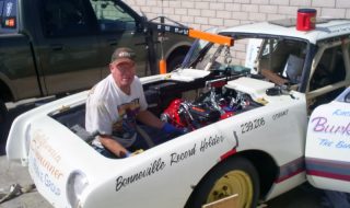
I'm going to put this out there up front... I will not be able to do this story justice. But, its such a great story and a cool car that you are going to get it and you are going to like it. Ok, I got that out, now on to the man and the machine. The man is cancer survivor and current cancer fighter Dan Sallia. The machine is the historic Burke Bros. Bonneville record holding 1962 Studebaker Avanti. I originally found Dan's story on landracing.com in a build thread he started there. That led me to his more detailed build thread on RacingStudebakers.com where I spent about 4 hours reading through the posts during 2 separate nights, checking out the pictures and soaking in one of the coolest car-guy stories I've ever heard. I knew I had to share it the MyRideisMe.com readers. Here's Dan working in the engine bay of the Stude. Now THAT is a setback motor! Dan has been racing against Cancer for about 4 years and has had 3 tumors. Recently another tumor was discovered, so Dan is working with his doctors (one doctor is actually a land...
Welding With DW: Setting A Base
posted by WelderSeries
One of the most important things about TIG welding (I think I say that a lot - there must be a lot of important things!) is keeping things steady. I've shot a video on keeping the filler steady so it doesn't get bumped into the tungsten and mess everything up, and now here's a video on using your hand as a sort of tripod to control your torch. I've used the writing analogy before, but here's another one: think about shooting a rifle. You don't get a steady shot by holding the gun with both hands on the stock - the muzzle would be waving around and there would be almost no way to prevent some movement. The best way to steady a rifle is to have some kind of support as close to the end of the muzzle as possible while still being able to fine tune your aim. Think of a welding torch in the same way - support the torch as close to the cup as possible without burning yourself. Of course, there will be compromises like visibility and pain. But to produce a good weld,...
Trident Speed Shop: Nara Prefecture, Japan
posted by Hechtspeed
I wanted to continue my international hot rod theme of late and share some pictures sent to me by Ken Sakata of Trident Speed Shop from Nara Prefecture, Japan. We first introduced you to Trident Speed Shop in Tano's '26 T roadster feature a few weeks back. In an email from Ken, he told me that Trident has been in business for 10 years. He was proud to say that he does not advertise in any magazines becaues he gets his business from word of mouth. Tano tells me that he takes his '26 T Roadster to Ken in Nara, which is on the opposite side of Japan from Sapporo, because Trident is the only shop he trusts with his hot rod. This black and white photo above is rad! This is Ken's roadster built in traditional hot rod style. I love these aircraft style windscreen frames, they really give hot rods that 1940's traditional feel dont they? Ken says he loves the speed culture. Hot Rods are very important in his life and he especially respects hot rodders. Here is Ken lubing crank bearings during reassembly. Anyone know what kind of engine this is? ...
Binary Engineering’s Evo – The Ultimate DIY
posted by Hechtspeed
Are you a "do-it-yourselfer" (DIY) hot rodder? Do you wrench on your own cars? Well, this is a DIY'er to the max. I came across pictures of Jared Drinkwater's Mitsubishi Evolution on NASIOC.com, a Subaru enthusiasts forum of all places. I'm a huge fan of the Mitsubish Evo for sure, but I was blown away at Jared's engineering and build skills. Jared is like the ultimate do-it-yourselfer. He is a Mechanical Engineer by day, by night he engineers parts for his Evo, which he races on road courses. Jared makes his own aero parts, race seat rails, fire extinguisher mounts, rebuilt his own engine (with a stroker kit and bigger turbo) and more. Dig these pics of his ride and Binary Eng parts you can buy for your own Evo. Jared's "Binary Engineering" Mitsubishi Evolution in his new race livery. Of course, he designed and applied these decals on his own. Dig the front aero package, designed and built by Jared using lots of aluminum sheet and carbon fiber. This was the stock front bumper. Jared has added a tow hook (just in case he needs help getting out of...

Bonneville Bound Louver Lover
posted by Hechtspeed
Bonneville Salt Flats: Car Show or Race Car? I've been wanting to share this car with you guys for a couple months now. I originally showed some early pics I took during a tour of Salt Flats Speed Shop (that story link here). Chris Davenport, shop owner and metal craftsman, and now louver expert, is building a '32 Sedan in the traditional style from the 40's and 50's. He has put together a pretty detailed build thread on the H.A.M.B. He has been updating it pretty regularly the last couple months as he's been making some big progress. Ok, enough of my words, let's see this work of hot rod art. Photos by Salt Flats Speed Shop. Check out them louvers. I think the top has 420 something louvers. Wow! It looks tough and right out of Bonneville 1946! Here's the view Chris will have when trekking out to the Salt Flats on I-15. I wanna grab some rolling shots of this ride when you drive out to Bonneville, k Chris? This might be my favorite shot. Add some black and white to this photo and it would appear...
Screamin’ Demon: BMI Racing’s Epic 4 Rotor Wankel Video
posted by Hechtspeed
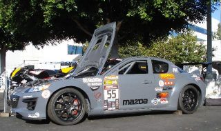
Yes, I did say Epic. Trust me, just listen to this video from BMI Racing! We wanted to show you BMI Racing, a Racing Team/Company who moved to the USA from Australia to pursue their racing dreams. Their plan is to build 2 Mazda RX-8 sport coupes each with a naturally aspirated 4 rotor engine (stock they come with 2 rotor engines and make 240hp), 1 car to compete in drifting and a 2nd car to race in Time Attack events. They have finished the first one and began testing this past summer. [youtube]http://www.youtube.com/watch?v=P4Fgi1OQqao[/youtube] Isn't it nuts that a crowd will cheer like that over an engine? It's the first RX-8 Renesis 4 rotor engine in the world right now. It sounds like an F1 engine, it just SCREAMS!!! What's a 4 rotor Wankel? Well, simply put, each RX8 engine has 2 rotors mounted in series. This 4 rotor is sort of a "big block" rotary with 4 rotors mounted in series, or 2 RX8 engines mounted in series. Cool right!? We don't have many details about the 4 rotor engine setup just yet. We hope to fill you in with the juicy rotary...
Salt Flats Speed Shop: Traditional Hot Rod Builder
posted by Hechtspeed
Salt Flats Speed Shop in Orem, Utah is run by Chris Davenport, a metal fabrication and finishing craftsman and hot rod builder who is dedicated to building 1930's traditional hot rods. Chris has been in business officially for about 2 years now and is attracting more and more customers as the word gets out about his affordable, high quality craftsmanship. "Need a Chop, a roof insert, fender, or a quarter panel? Well you've come to the right place. We'll fix all your cars issues, and have it looking as good in "bare metal" as it did when it was made." Chris (in the white shirt) showing us around his shop in Orem. This is a customers 3 window coupe with suicide doors. We dropped in on Chris Thanksgiving week. He willingly took an hour or more to give us the full shop tour. He explained all his tools, showed us all his projects and talked shop. I could tell Chris is passionate about hot rods! I had emailed Chris letting him know that a friend and I wanted to drop in and check out his shop. My friend, Gary, has a 1928 Model A Pickup of his own...